
makeCahoots
Cologne area, Germany
Cologne area, Germany
Recently Make magazine featured an article about a bat monitor. I have a lot of those guys flying around my balcony at night, so I was intrigued to listen to them chirping around in the ultra-sonic part of the sound spectrum.
The amplifier circuit around a Knowles MEMS mic presented there looked practical, but too simple and not reaching its potential in some ways that I could just not copy when building one for myself (too many amps just not doing enough). So I will let you know how I adapted it to give a corrected frequency response adjusted to the characteristics of the microphone. That's it, also nothing fancy, but a neat little project to dive into some interesting topics with room and ideas for follow-ups.
Work in progress / parts still in concept phase ("open" section)
...if anyone wants to join. I had some of the mic + amplifier boards built. I could provide you with a working board ready to interface any 3.3V powered µC with fast enough ADCs. Contact me via PM.
The microphone chosen for this task is a Knowles SPU0410LR5H-QB. It features an analog output and is mainly chosen for being specified over a frequency range of up to 80kHz and featuring an analog output that lets us make use of the full bandwidth. The frequency response is shown here to lay the basis for the following circuit development.

It shows a significant narrowish peak in sensitivity around 23kHz and a wide dip with a minimum at around 60kHz. It is normalised to the sensitivity at 10kHz, below it is nearly perfectly flat down to 100 Hz.
I have developed a circuit that can be used to accurately correct for this frequency response and amplify the output to a level usable by a 3.3V referenced ADC.
The nominal sensitivity at 10kHz is -38dBV/Pa, which corresponds to 12.6mV/Pa. The human hearing threshold is often stated at 20µPa, that is widely used for sound pressure reference. This means the lowest humanly detectable level would give:
V(humanth) = 12.6mV/Pa * 20µPa = 252nV
Wikipedia compared this threshold to a mosquito flying at a distance of 3m. Since hearing is not linear and I think I can remember something about a detectable difference in volume is reached by doubling the sound pressure. Hope that is close to correct, otherwise please let me know. This would mean +6dB. So let us go a few "volume steps" up from the mosquito, I imagine a bat to be quite a bit louder.
Four of these steps up gives:
V(batassumed) = 24dB * 12.6mV/Pa * 20µPa = 200mV / Pa * 20µPa = 4µV
I will start off by setting the gain at around 400. This will give 1.6mV for this lower limit, which will probably not be properly detectable. A full scale value would correspond to:
fullScaleLevel = 1.65V / 400 = 4.125mV = 60.3dB (referenced to assumed bat minimum) = 84.3 dB (referenced to humanth)
60dB seems a lot for bat singing, but we also started at 3m distance and I want to listen to them from a safer distance :-)
I will try it with this gain and let you know how loud they are.
The amplifier will have the task to amplify the signal with a gain of 400 in the range from 10kHz to 80kHz. it shall adjust for the frequency dependent sensitivity of the mic. I will show the whole circuit first and then go through a few parts.

The simulation file can be found in the files section.
The configuration nicely equalising the mic is shown here (still shown for a gain of 100 or 40dB, frequency characteristic unchanged):

The range of possible configurations is depicted in this stepped simulation.

This displays the envelope that can be covered with the current configuration by only adjusting the potentiometer ratios. Enough to adequately compensate for most MEMS mics' frequency responses. The stage quality factor and centre frequency can easily be modified by changing a few capacitors and resistors. More details about that can be found in TI's audio circuits collection part 3.
After We have seen what the circuit can do for us, it is time to say a few words about how it is doing it. I will not go into details. So feel free to ask, if anything is left unexplained that you are interested in discussions.
The first two stages are simple inverting amplifier configurations with optional low pass filtering. The mic output is ac couple to the gain stages.
The more interesting part is the third stage that features two band pass filters. The resistor pairs R9, R11 and R15, R16 are used to simulate an adjustable potentiometer. This is used to set gain or attenuation for a specific frequency band. The band is mainly defined by the capacitor C8 (simulation circuit) and usually a quite large inductance which is replaced by a negative impedance converter, making the capacitor C9 act as a coil. A more detailed description is available in the aforementioned TI paper and even more detailed info on the NIC configuration can be found by searching for that term in your favourite search engine (I am still thinking about whether to write an article about this or not).
Stages can be added in parallel as needed to get the intended shape of frequency response. A potentiometer in mid position leaves the response flat and unchanged.
I started off by stating that not all of the four amplifiers used in make magazine's version were put to optimum use. Now count carefully, the simulated circuit even uses five opamps. The frequency response shown by our mic can sufficiently be corrected by adjusting overall gain and taking care of that huge peak at around 22kHz.
Therefore the circuit I will describe in the following and turned into an actual proto pcb will only use one equaliser stage. In general the circuit shown in the simulation can be extended by as many stages/bands in parallel as needed to shape the response. I will put it in the files sections, so you can use it as a base.
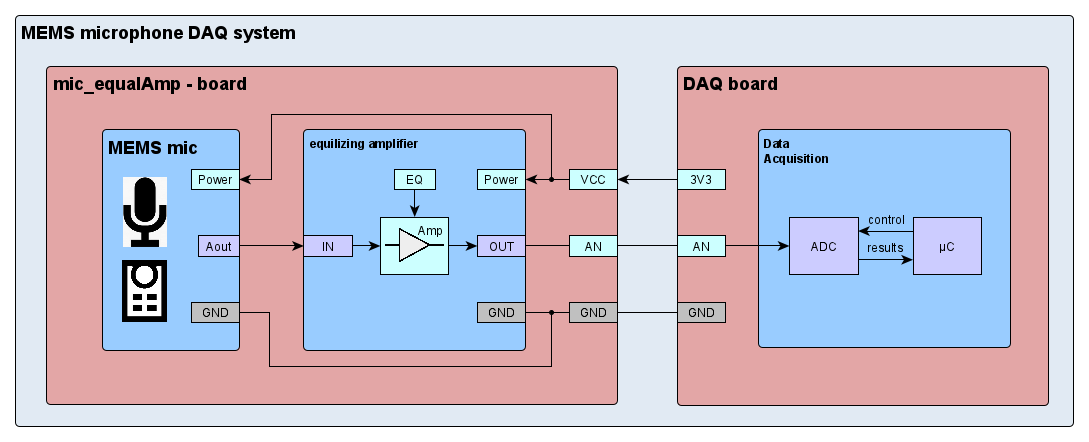
For the interface I decided to offer 3-pin header and a JST connector usually used for the STEMMA interface. The component is not STEMMA compliant, since it cannot take 5V as a supply voltage, but the connectors are a nice alternative. I stuck with the standard pin out to keep it at least partially compatible.


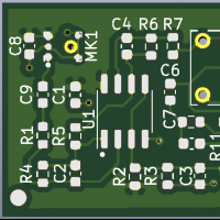
finally this is what the PCB looks like:

gitHub - makeCahoots/communityProjects
TI's audio circuits collection part 3
Knowles SPU0410LR5H-QB MEMS microphone
T362 - solder reflow heater
Chip Quik TS391AX - solder paste